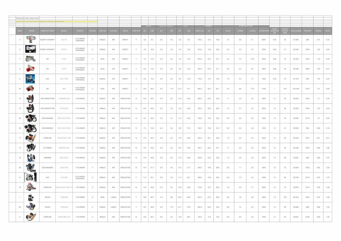
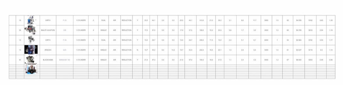
01 Engines for Ultralight Aircraft
Which engine to use depends on a lot of factors such as the airframe, the gross weight, the intended mission, etc… There are many different engines that have been tried on aircraft. Some were made for aircraft, some were made for other purposes. In the experimental aircraft world we have the freedom to use any engine we would like, no matter how crazy!
The purpose of this article is to show the options that are currently available and in common use with a good safety record. To choose a correct engine, first we must look at the intended mission. Small Engines for the Q1 should be hard to find but please find below a short cross over about currently (Feb 2021) available Engines that maybe will fit to a Quickie Q1.
|
| ||||
02 Alternative Engine to that list from the top
Unfortunately the engine I choice at first, it was a Rotax 503 with around 45kg (all in), doesn't work for me because at the limitation of weight. It's not allowed to cross the max. weight of 120kg for the airplane based on the government restriction here in Germany. The other Rotax engine like 477 or 377 also do not works for me, so I did another investigation about eligible Engines that would fit my budget too.
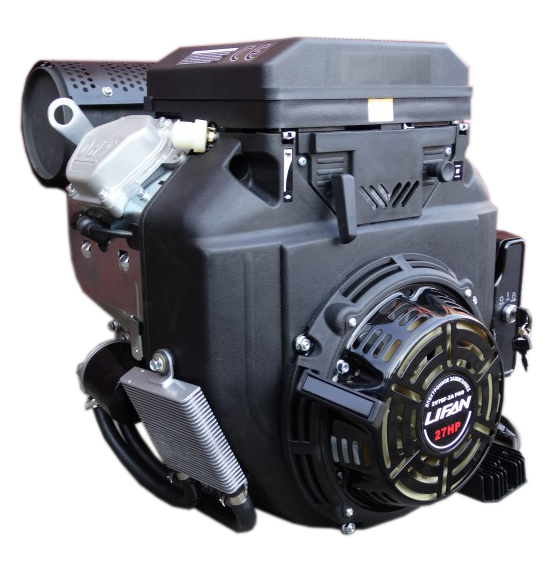
So in the end I did the choice to a Lifan engine (horizontal shaft) that will be in the range of a total weight around 31kg, after the no needed stuff are move out. The standard horse power is come around 23 hp, but with some modification it will be reachable a performance about 30hp. So that contribution will support the Q1 very well with a reasonable price for all the stuff is needed to make it truth.
LIFAN 2V78F-2A Pro - 27hp & 3amp alternator
Features:
Unfortunately the engine I choice at first, it was a Rotax 503 with around 45kg (all in), doesn't work for me because at the limitation of weight. It's not allowed to cross the max. weight of 120kg for the airplane based on the government restriction here in Germany. The other Rotax engine like 477 or 377 also do not works for me, so I did another investigation about eligible Engines that would fit my budget too.
So in the end I did the choice to a Lifan engine (horizontal shaft) that will be in the range of a total weight around 31kg, after the no needed stuff are move out. The standard horse power is come around 23 hp, but with some modification it will be reachable a performance about 30hp. So that contribution will support the Q1 very well with a reasonable price for all the stuff is needed to make it truth.
LIFAN 2V78F-2A Pro - 27hp & 3amp alternator
Features:
- Manufacturers Code: 2V78F-2-2A PRO
- Manufacturer: LIFAN
- Weight: 47 kg
- Main shaft: horizontal
- Dimension: 455 x 400 x 450 mm
- Fuel consumption: 370 g/kWh
- Volume: 688 cm3
- Compression ratio: 8,5:1
- Piston stroke: 72 mm
- Typ of Engine: 2-cylinder, petrol fuel
- Ignition system:contactless semiconductor
- Power: 27 hp
- Starting: electrical & manual
- Cylinder diameter: 78 mm
- Shaft diameter: 25 mm
- Coil: 3 A
- Equipment: oil pressure sensor & oil cooler
- Nominal Power: 15 KW
- Maximal power at 3600 rpm: 16 KW
- Max. Torque at 2500 rpm: 43,5 Nm
- Volume of oil crankcase: 1,4 l


03 Belt drive analysis and drawings
Please find below some information about Belt drive Systems and figures.
a. Light sport aircraft belt reduction drive 2009
b. 2.58 BELT DRIVE PLANS – 1 pdf file with 14 drawings
c. 3.35 BELT DRIVE PLANS - 1 pdf file with 14 drawings
d. WATER JET CUTTING FILE – 1 dxf file mm 1:1 scale
Building the belt drive reduction is a relatively easy task with a few tricky parts which we will cover here. All drawings are for a flat 16РК multi-V belt. We have tested these configurations and know them to work with no issues whatsoever. The Belt drives from the plans slightly differ from the ones in the pictures. The drawings of the belt drives were optimized, so that the expensive and unnecessary machining was removed. The plans of the 2.58 and 3.35 belt drives are in PDF format, with 14 drawings in each file. The belt drives were calculated only for pusher propeller and MUST NOT be used in any other configuration!
You need a CCW propeller !
BELT DRIVE 2.58 ratio - this setup is suitable for smaller, faster propellers turning at about 2900 – 3000 RPM. We have successfully tested this configuration with e-props NG-D adjustable propeller 3 blade 150 and e-props 2 blade not adjustable 145 – noisy but weight 850 gr. only !!! 2.58 drive it is not suitable for e-props NG-D 1.60 due to high peripheral speed (this is already tested).
BELT DRIVE 3.35 ratio for Silverwing FSJ600-PF01E – this setup is suitable for large, slower propellers turning at 2400 – 2450 RPM. In reality this describes most of the propellers rated for and around 50 horse power that are available on the market . Their diameter ranges between 1.55 and 1.65 meters for both wood and composite. This type of propeller requires slower turning speeds in order to guarantee the smooth operation of the engine at 7500 – 8200 max RPM with propeller peripheral speed staying under 0.6 MAX.
Key Build Tips
The main thing with the belt drive is to create a sturdy frame of solid aluminum to support the drive pulleys and the damping pulleys. The drive must be equipped with the speed sensor. For best results, the pulleys should be fabricated on a CNC lathe to guarantee equal spacing of the grooves. The same can be done on a manually operated lathe but would require precision craftsmanship.
Materials
We recommend using the materials specified in the plans or replacing them with equivalent ones. These materials, apart from being used in the 3D simulations, have been flight-tested, which is most important here.
Frame
According to the design, the base frame is to be cut out from a solid 30mm sheet of AW 7075 material using a water-jet cutter and then finished with a milling machine.
The cutting operations can be performed on a CNC machine, which is the more expensive option, or by hand using model from the drawings , which is very labor-intensive.
The file attached is in a universal digital format and can be used to cut out the base frame on a waterjet cutter or CNC machine, or can be printed out to make model. If you have decided to cut the frame out by hand using model, print the file from AUTOCAD or other software on 160gr/m2 paper (or heavier) in a 1:1 scale and you will have your model.
Eccentric Tension Shaft
It is very important to fabricate the eccentric shaft to a very high standard of precision. The axes of the two cylinders of component from the plans P5 must be dead parallel. If this requirement is not met, the surfaces of the upper and the lower pulley will not line up causing unacceptable twisting of the belt.
Cutting the Spines and Fabricating the Crankshaft Pulley
This is the most complex and hard to make part in the entire build. Cutting internal splines, is a difficult thing to do and few machine shops have the right equipment for the job. The splines on the crankshaft of the engine are not standard. In the drawings we have provided the necessary allowances, but the splines must be cut depending on the crankshaft .
Crankshaft pulley with plasma nitriding – thousands of hours without wear
Update – Very interesting information - Engine splines are the same as those from the hub wheel of
HYUNDAI ACCENT 95 - 99 /Excel / Elantra (SPD) / #27004528
Rubber Mounts
The upper rubber mounts of the belt drive are intended to support the force created by the propeller. It is very important to use these mounts because they do not allow the engine to twist under the thrust from the propeller. The design of the lower mounts depends on the particular aircraft you are building. We recommend using the original mounts, if possible.There is a tested solution using a sub frame under the engine resting on four mounts as ROTAX engines does. Choose soft mounts similar to the original ones.
Source: http://ppgtrike.com/belt-reduction/
|
|
|
| ||||||||
