|
Chapter 01 Foam Allocation Plan - AIREX C70.55
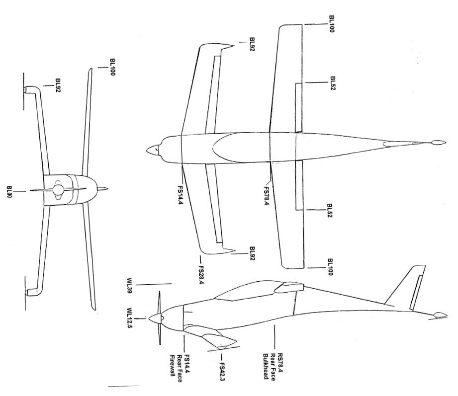
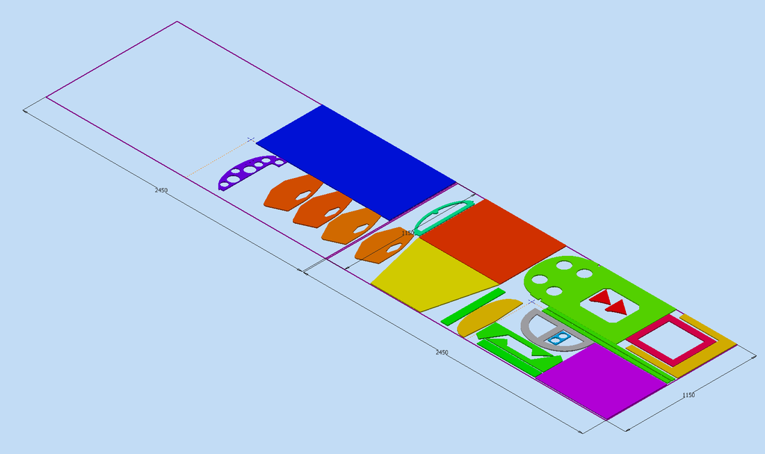
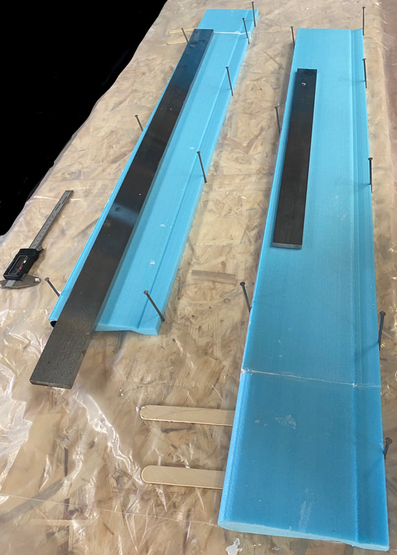
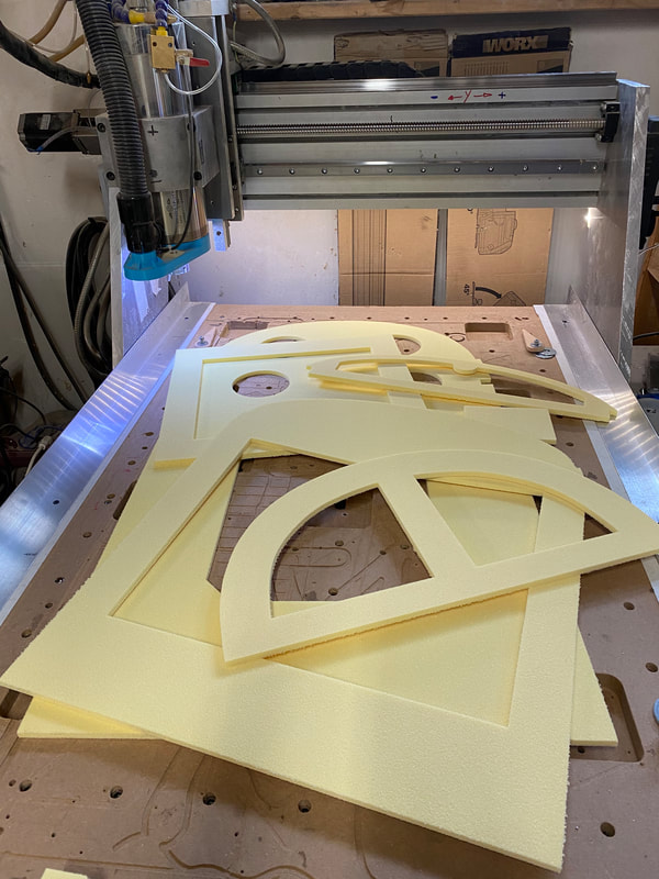
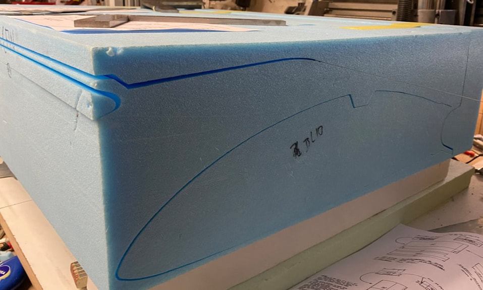
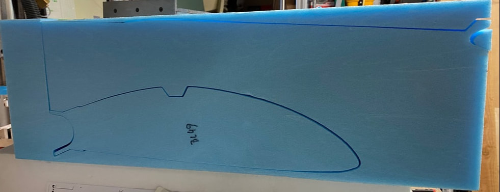
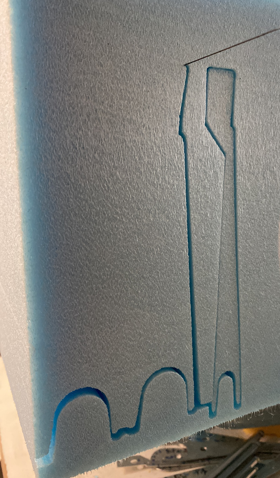
Enclosed is the new layout plan for the AirEx C70.55 panels, which are supplied by Gaugler & Lutz in the dimensions 2450 mm x 1150 mm. This became necessary because the dimensions 1542 mm x 585mm and 381 mm x 585 mm specified in the drawings are not available or only at an extra charge. The production of the parts on the milling machine can now start after the machine code has been created. The layout plan include the following parts:
|
|
Chapter 03 - Education
Building the RUTAN Composites - by Ferde Grofe, presented by Burt Rutan and Mike Melvill. Watch this video before start build any parts for your Rutan Project.
Building the RUTAN Composites - by Ferde Grofe, presented by Burt Rutan and Mike Melvill. Watch this video before start build any parts for your Rutan Project.
Chapter 06 -Ailerons - Right and Left
Chapter 07 - Fuselage
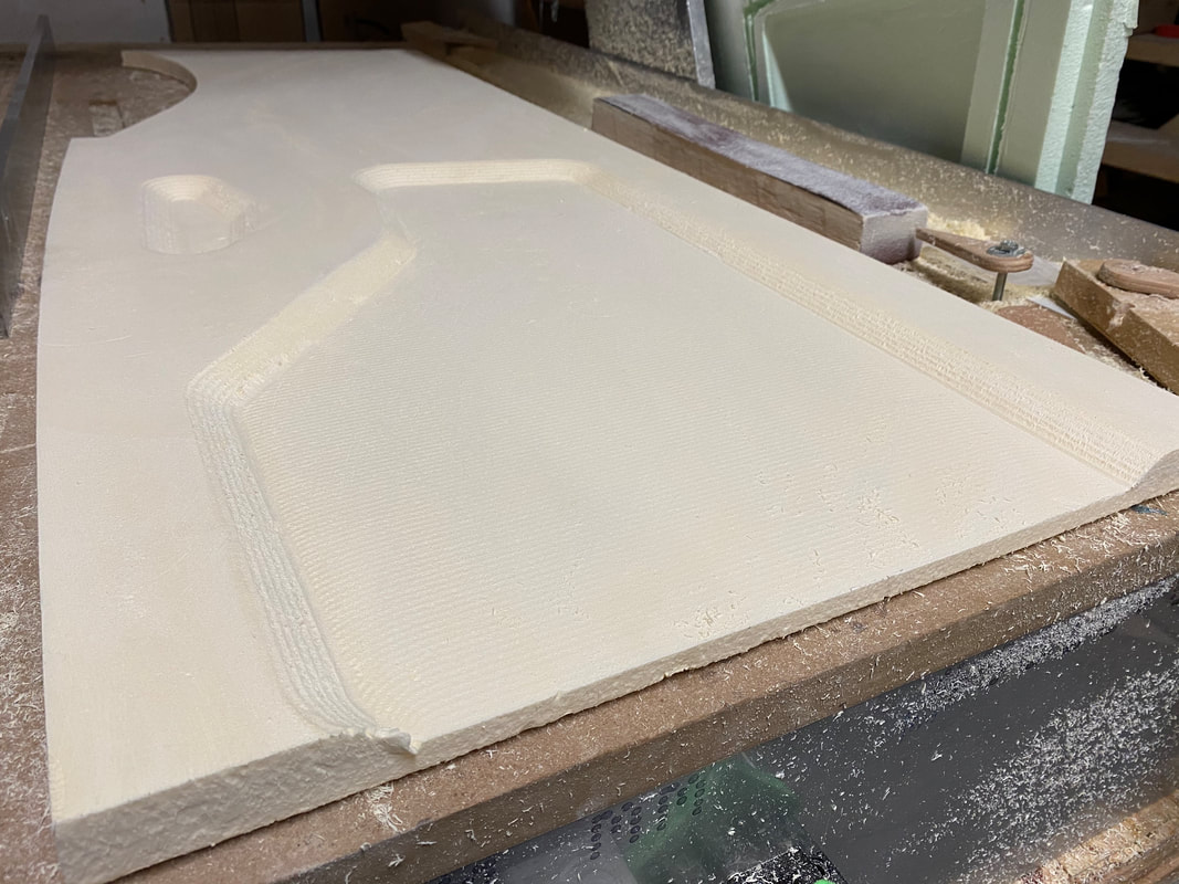
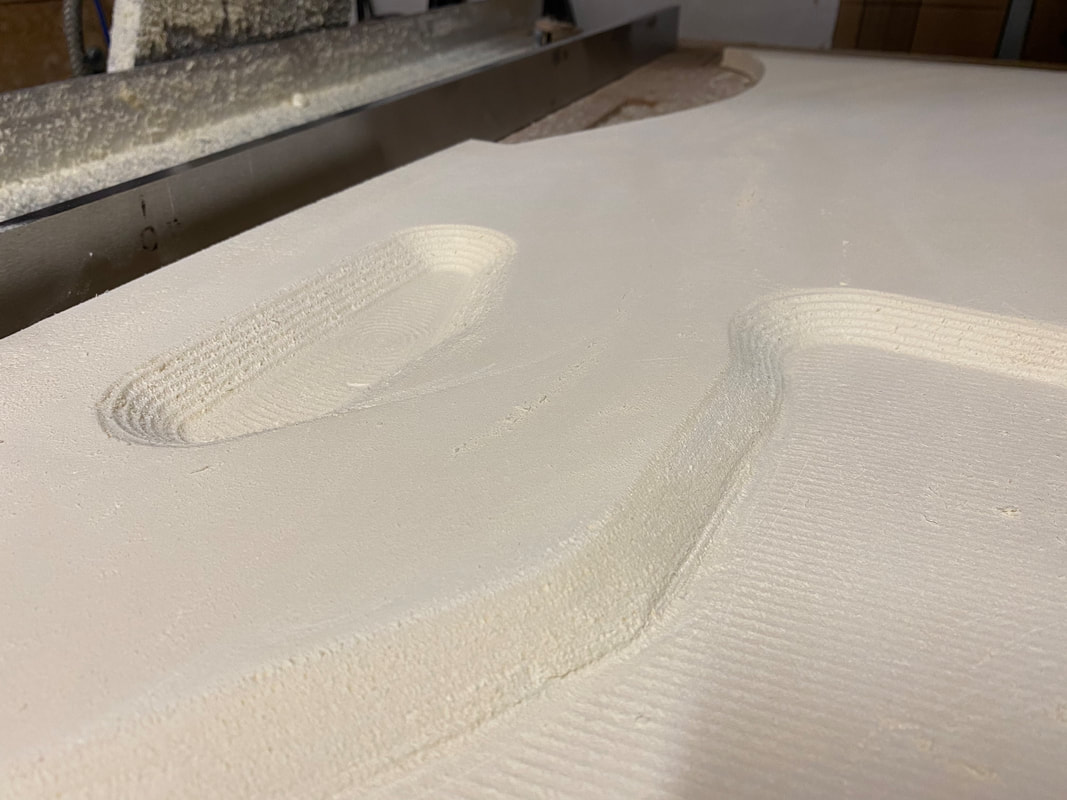
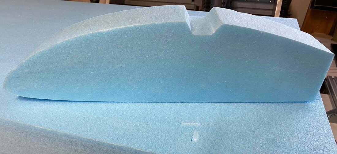
Enclosed is the result of another test with optimised settings and tools for machining a URSA rigid foam board XPS, which comes closest to the BAUDER E33. I think the result is quite good and the final machining can now start. For the test I used a Ball-mill with a diameter of 8mm. However, the individual steps in the foam are still easy to additional sand all requested area.
Enclosed is the result of another test with optimised settings and tools for machining a URSA rigid foam board XPS, which comes closest to the BAUDER E33. I think the result is quite good and the final machining can now start. For the test I used a Ball-mill with a diameter of 8mm. However, the individual steps in the foam are still easy to additional sand all requested area.
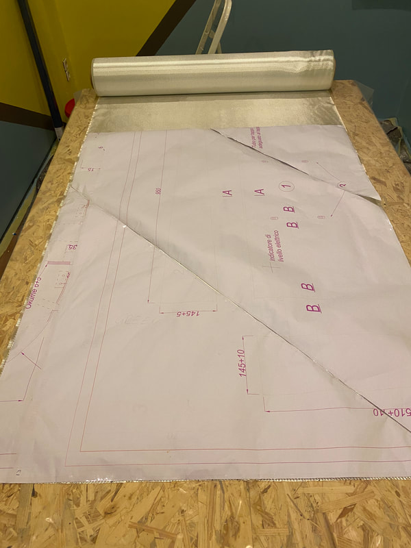
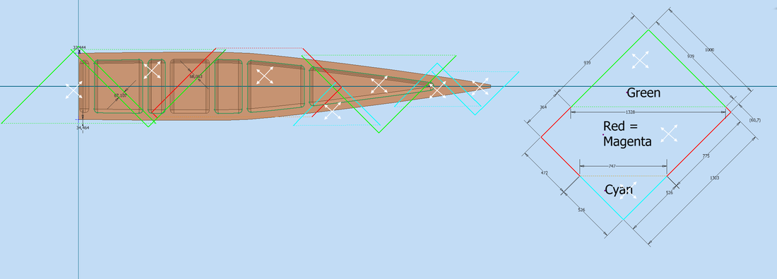
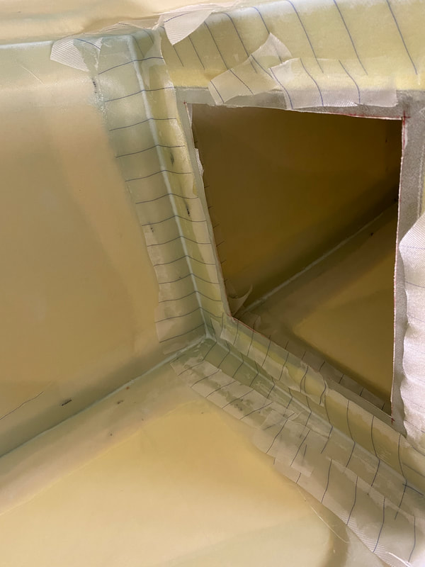
Layout plan for bid-glass to glassing the fuselage in the request of 45° to WL15 to reduce scrap. The overlapping of each glass is schedule to around 50mm or 2" .
|
Pattern laid out on glass and ready to mark with a felt-tip pen, then cut out the individual segments.
|
|
Layout plan for bid-glass to glassing the fuselage Bottom, in the request of 45° to WL15 to reduce scrap. The overlapping of each glass is schedule to around 50mm or 2" .
|
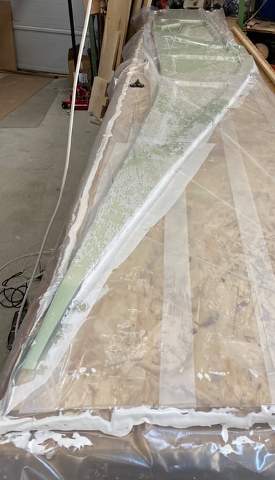
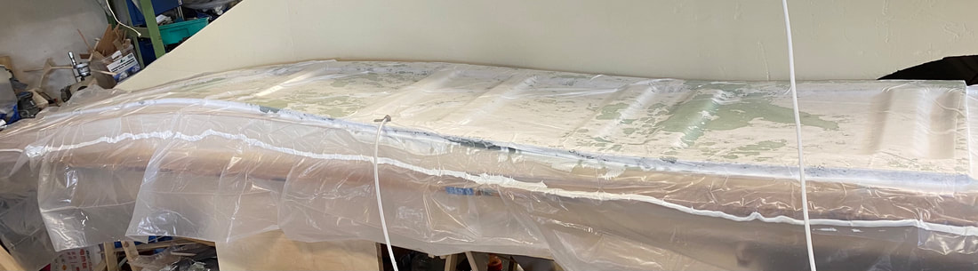
The first side of the fuselage is packed in a vacuum bag and is now curing. The film is a standard film from the hardware store and the film was sealed with acrylic. Since it is still a bit cold in the workshop at night, heating blankets have been placed on the vacuum bag. They quickly reaches 30 ° C and the curing takes place under very good conditions.
From today's point of view, I would apply the pine strip 19 x 19 x 1882 mm before laminating, because it is very often slipped. Also I would put more Compoflex 150 or additionally standard absorbent fleece to absorb the excess resin. Fortunately the sides are covered with Duck-tape, otherwise glass would be glued to these surfaces. I used an 18 cm squeezee, but it is too big and heavy for these job. For large and flat surfaces this one is very good. As soon as resin gets on the puller in the area of the gripping points, the squeezee starts to slip. |
|
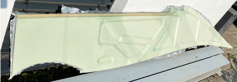
The fuselage side is now moved from the vacuum bag and ready to cut off the overhanging glass parts to get a clear side unit for the further fuselage assembly steps.
|
So far the second fuselage side is in the bag and will stay for the next 24h in it. Additional to that some heating blankets have been placed on the vacuum bag. They quickly reaches 30 ° C and the curing takes place under very good conditions.
|
|
The bottom section is in the bag for 24h. In the picture from left side the bottom unit is ready to place glass on it. The picture right show up the bottom unit already placed in the bag with one bid 45°. But before the bottom is ready to go for the next step it need a assembly table based on the bottom wave of the fuselage. Please find below the picture.
Bottom assembly table before place the bag and the bottom.
The bag and the bottom is already placed to go the next step.
|
The bag is closed and vacuum is in for the next 24h.
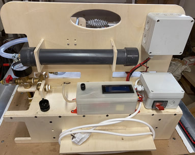
My homemade vacuum pump turned out to be really helpful in the process. With the pressure switch, a successful solution. Please follow the link for the constraction drawings.
|
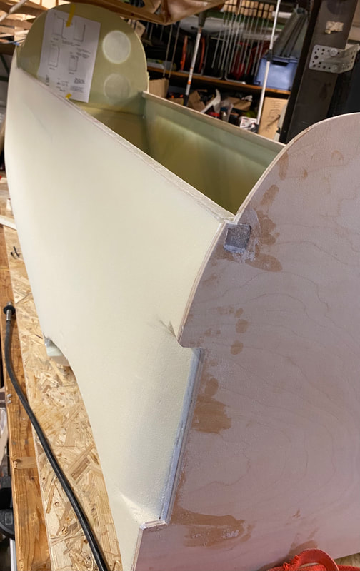
So far the assembly of the fuselage start with the two sides, bottom, bulkheads and the firewall. For the further assembly I used the wave-shaped console, which was already used for the production of the bottom. This has proven to be very useful and has given the entire assembly a very good fixation. To secure the frames, I used the clamps I built myself to help the curing process. Some timbers have additionally held the sidewalls to ensure positioning to the bottom unit as well.
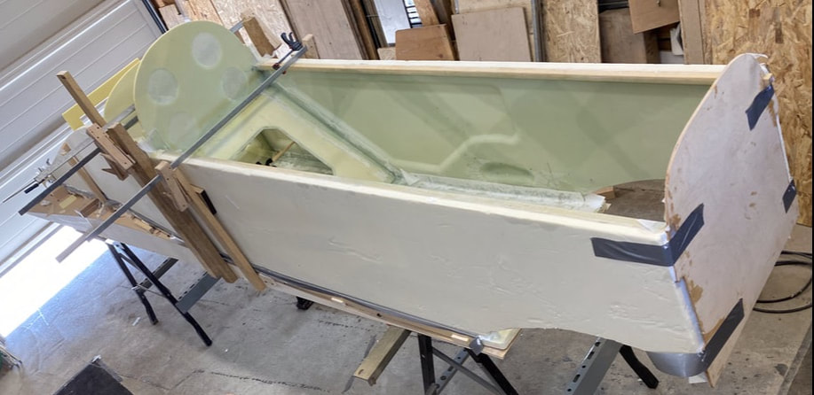
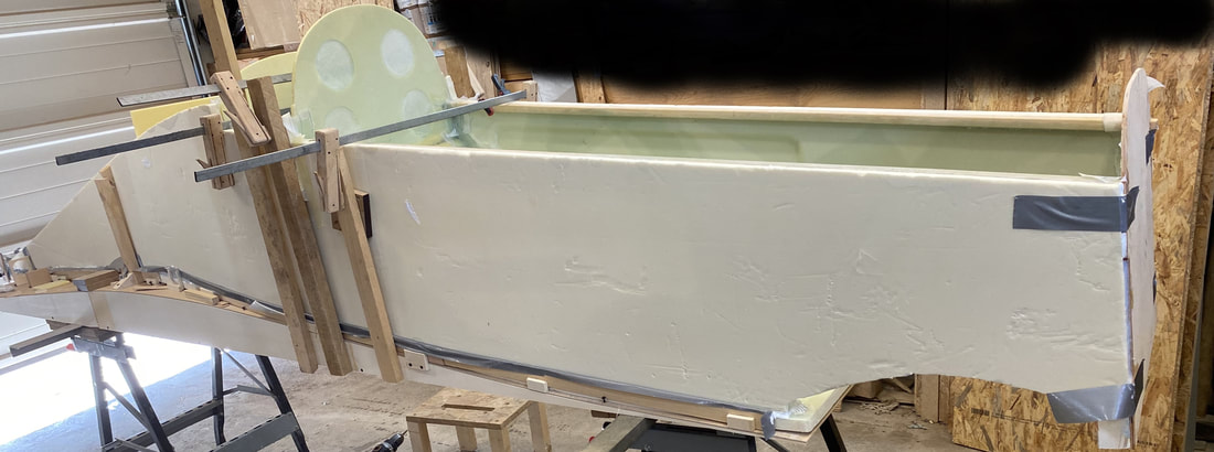
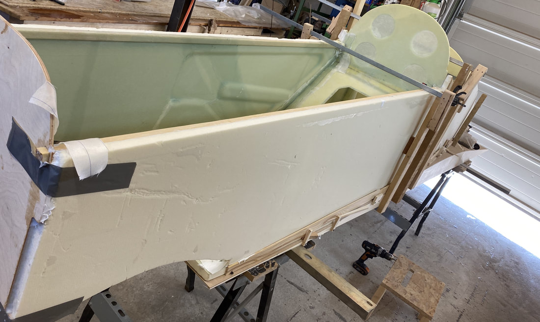
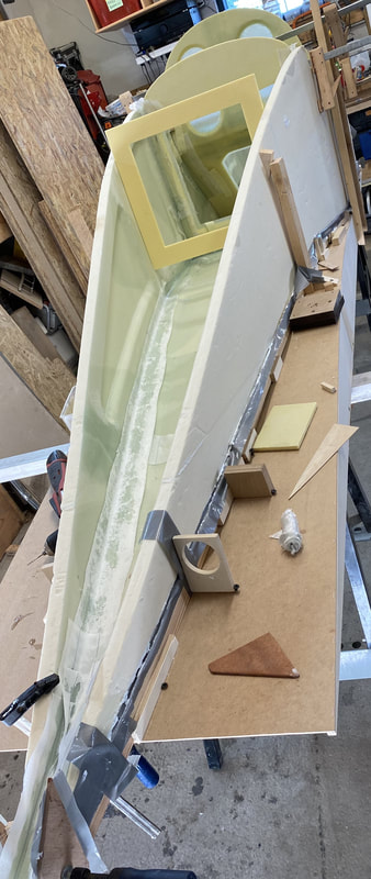
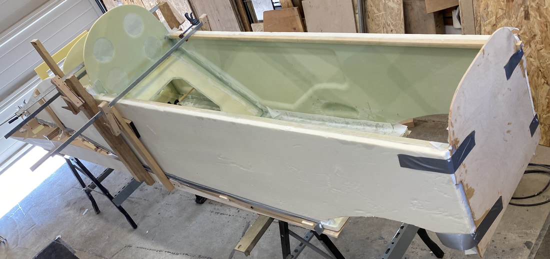
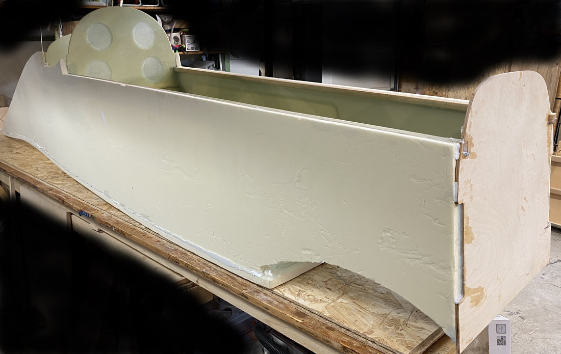
The last bulkhead is in his place and so far the fuselage is ready to sand the outside surface and curve the unique Q1 lines.
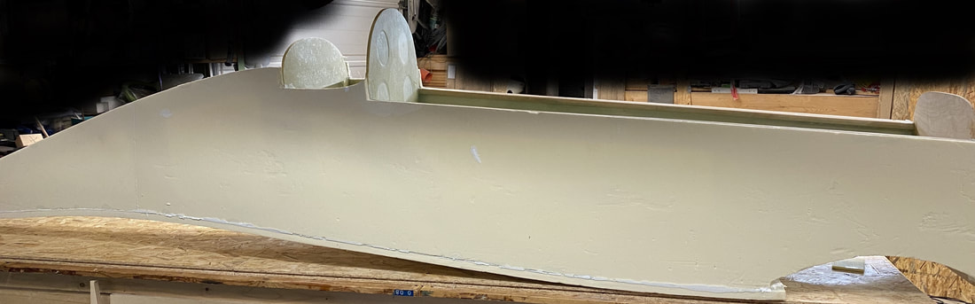
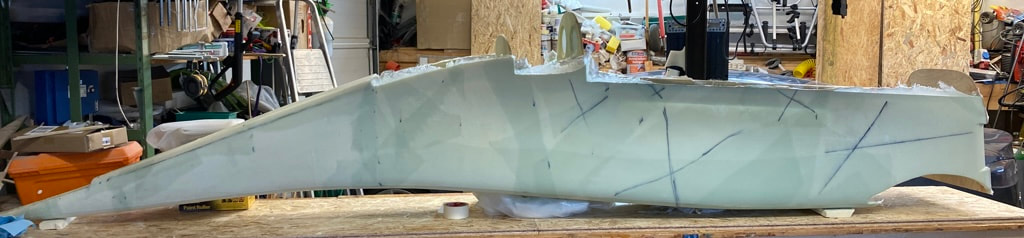
In the meantime, the grinding of the contours on the Q1 has started, the first three corners are sanded, enclosed are some pictures.
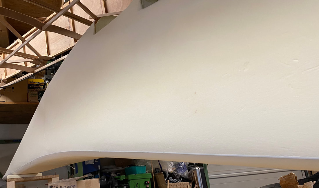
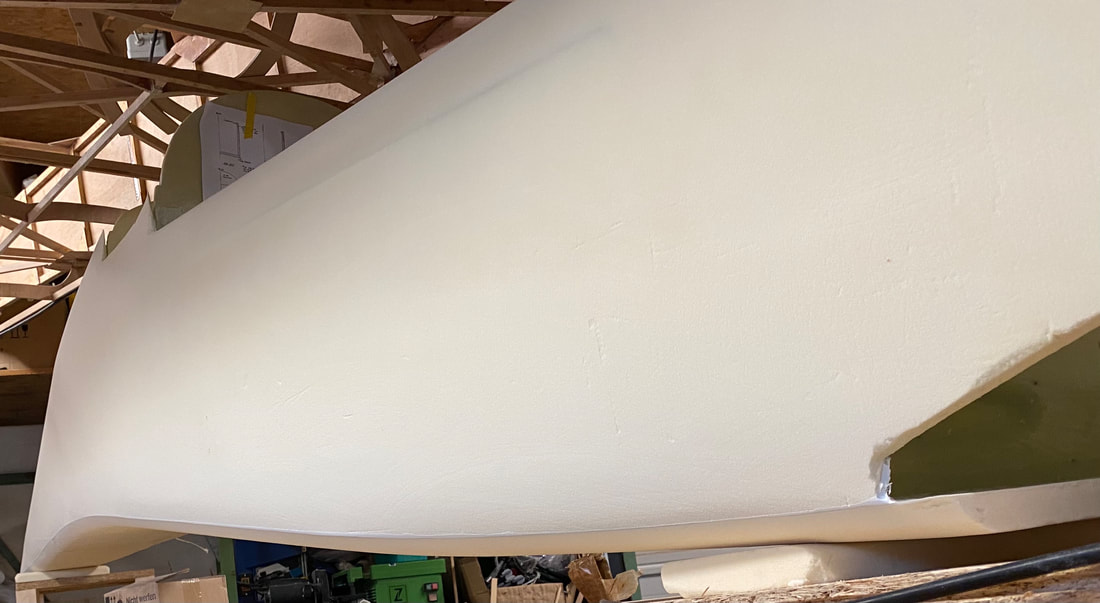
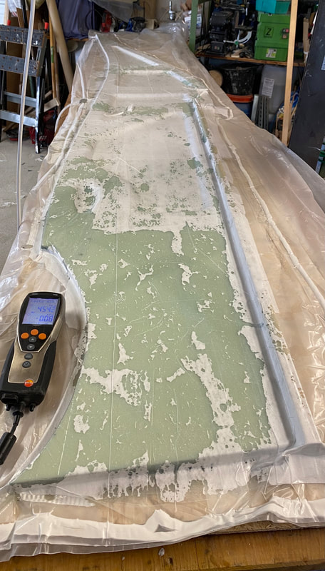
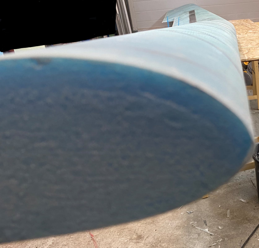
Sanding the foam was not very strenuous, but in combination with the very hard micro and the glass fibers a real challenge from purposeful pressure as well as guiding the sanding block. So far the second side is now also sanded, so the fuselage is ready for the next step, the application of the glass. But before going any further I will weigh the hull to understand how much glass and epoxy was applied in the next step.
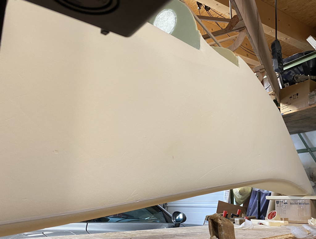
The fuselage glassing is for the outside done so far.
Chapter 07 - Bulkheads
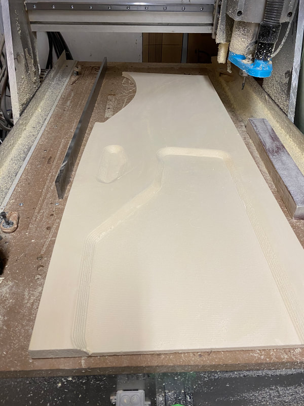
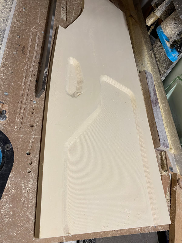
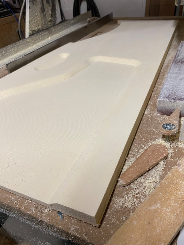
Enclosed you will find some pictures from the production of the bulkheads with the inclusion of the milling machine, the material is Airex C70.55 .
Enclosed you will find some pictures from the production of the bulkheads with the inclusion of the milling machine, the material is Airex C70.55 .
FS89
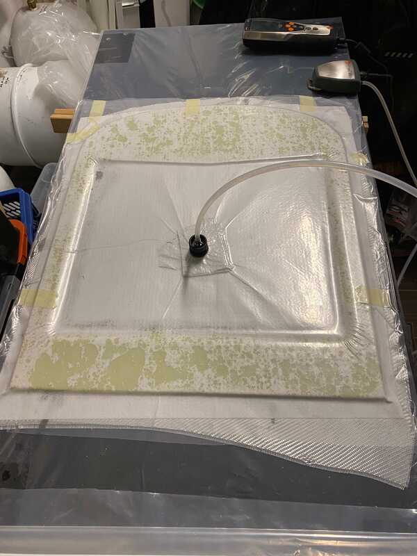
The Bulkhead FS 89 is already fixed in Vakuum bag.
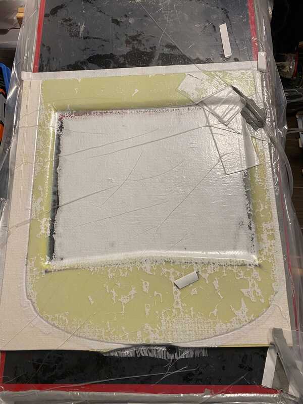
At first I mixed resin with a lot of 40,5g and separate 20g for micro and 20,5g for glass, but after the first 20g for micro was spread I need to go with the other 20,5g. After that the foam was „wet“ and every part of it was filled. The foam (Airex C70.55) is highly absorbent. After that I need to mix another 40.5g to fill the glass, remember the laminate calculator from R&G indicate a total resin demand of 29g for the FS89 bulkhead. So there is a gap between the calculator and that what I need in the end about 279%.
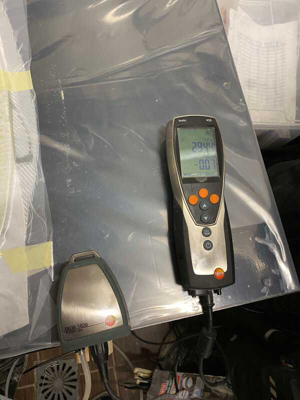
The foam weight naked is 82g, with the micro is 126g, the glass (insert not cut out yet) was 98,57g, the second load of resin was 40,5g, so currently the first layer include micro/resin and glass is around 265,7g. Additional to that I place on layer Compoflex to absorb the unnecessary resin form the surface and the vacuum is fixed at 840hPa.
For more information about weight of each part, please visit the Q1 weight section: aerobase.weebly.com/q1-weight.html
The Bulkhead FS 89 is already fixed in Vakuum bag.
At first I mixed resin with a lot of 40,5g and separate 20g for micro and 20,5g for glass, but after the first 20g for micro was spread I need to go with the other 20,5g. After that the foam was „wet“ and every part of it was filled. The foam (Airex C70.55) is highly absorbent. After that I need to mix another 40.5g to fill the glass, remember the laminate calculator from R&G indicate a total resin demand of 29g for the FS89 bulkhead. So there is a gap between the calculator and that what I need in the end about 279%.
The foam weight naked is 82g, with the micro is 126g, the glass (insert not cut out yet) was 98,57g, the second load of resin was 40,5g, so currently the first layer include micro/resin and glass is around 265,7g. Additional to that I place on layer Compoflex to absorb the unnecessary resin form the surface and the vacuum is fixed at 840hPa.
For more information about weight of each part, please visit the Q1 weight section: aerobase.weebly.com/q1-weight.html
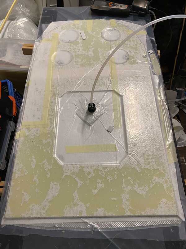
FS89 - Vaccum bag is closed
|
FS89 - Vacuum bag after 12h.
|
F110 Bulkhead
The 110 was in the beginning not glass nor with resin, like the plans indicate. But in the assembly process of the fuselage it make not sense to stay the bulkhead without glass and fixed it like the other. So I did the glass and resin on in and place it on vacuum for 24h to fit the bulkhead on the next day in the fuselage. That will work better than the plans indicate.
The 110 was in the beginning not glass nor with resin, like the plans indicate. But in the assembly process of the fuselage it make not sense to stay the bulkhead without glass and fixed it like the other. So I did the glass and resin on in and place it on vacuum for 24h to fit the bulkhead on the next day in the fuselage. That will work better than the plans indicate.
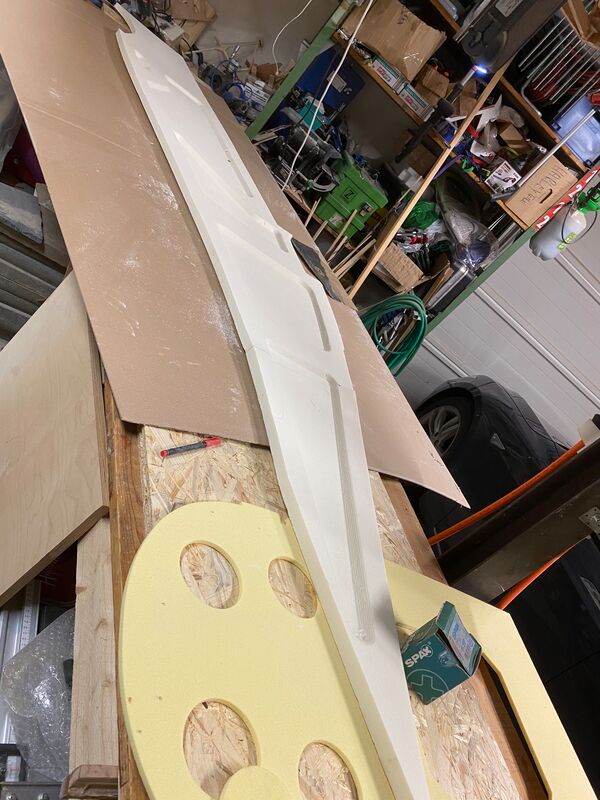
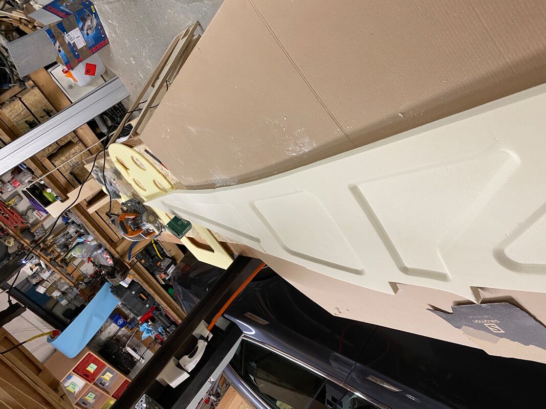
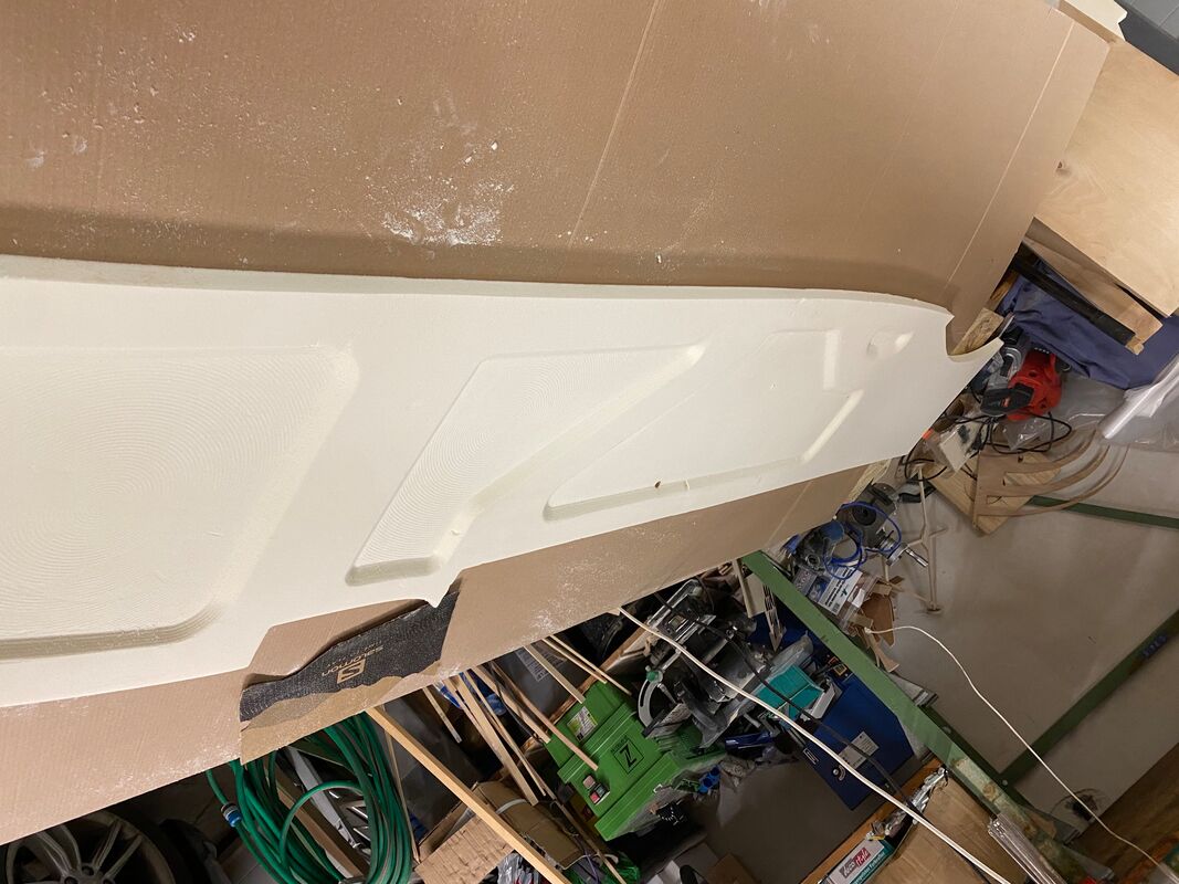
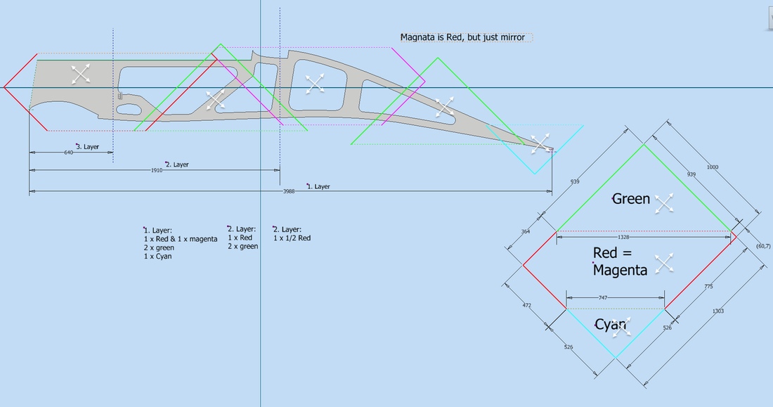
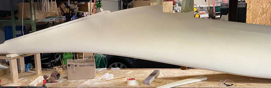
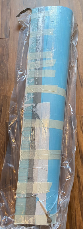
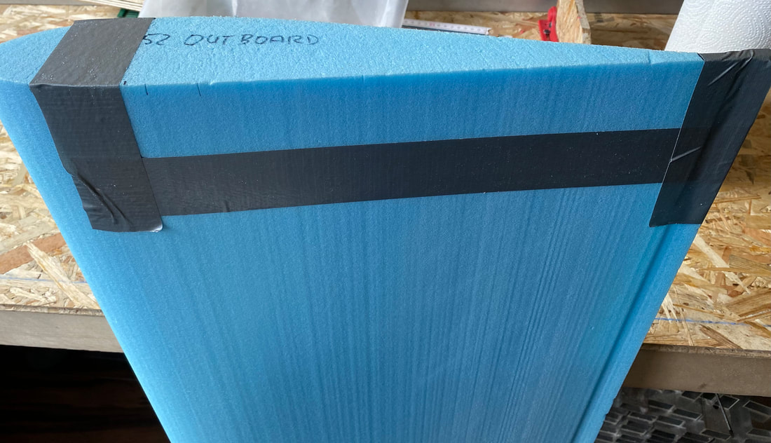
Chapter 07 - Canard & Wing Foam Cutting
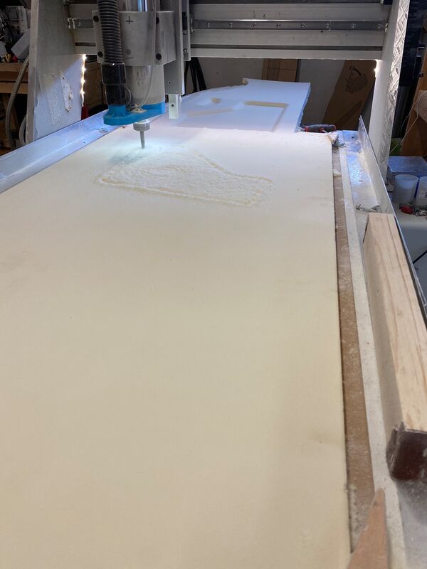
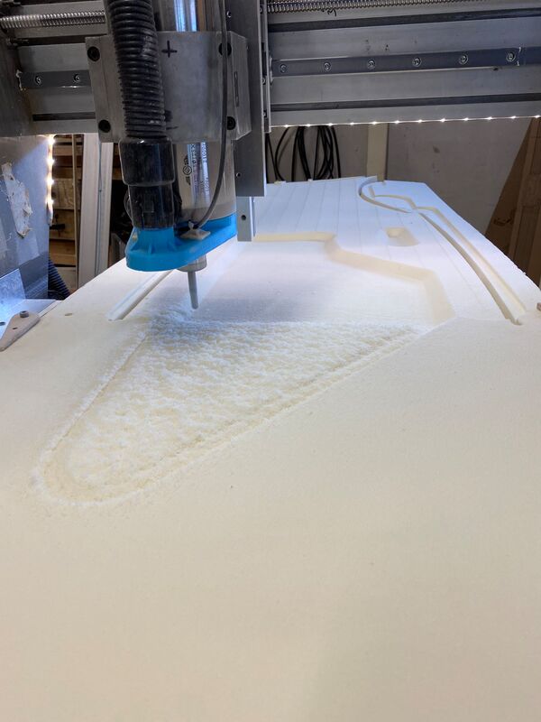
So far the Canard is going truth the cnc diy foam cutting machine, please find a picture below. After that the wing will be the next step to cut. The cnc diy foam cutting machine based on that source: RcKeith and that software: https://www.devcad.com/eng/devcncfoam.asp The machine runs very well and bring out a good quality of cuttet parts. How to build part#1
So far the Canard is going truth the cnc diy foam cutting machine, please find a picture below. After that the wing will be the next step to cut. The cnc diy foam cutting machine based on that source: RcKeith and that software: https://www.devcad.com/eng/devcncfoam.asp The machine runs very well and bring out a good quality of cuttet parts. How to build part#1
Part of the Canard Center section to test the CNC Foam Cutter settings.
|
|
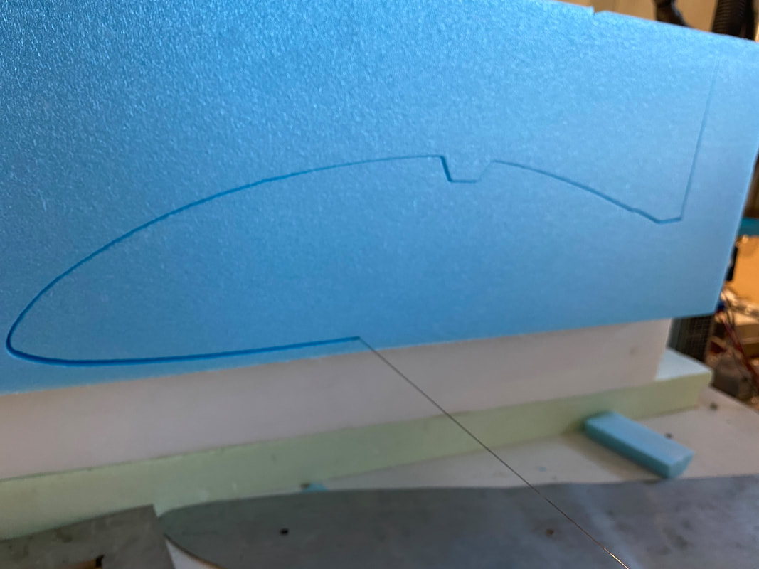
Elevator Foam Cut
|
Chapter 07 - Fuel Tank Epoxy resin C - Chemical resistant laminating and coating resin Description: Solvent and filler free High chemical resistance Epoxy Resin C is a cold-curing, high-viscosity (viscous), solvent- and filler-free laminating and coating resin with very good chemical resistance to numerous substances. Chemical resistant components and coatings such as tanks, vessels, pipelines, floors, transport vehicles. The resin is suitable for coating and for hand lamination, winding and pressing (also in vacuum). Processing: The system does not contain the reactive thinners normally used in laminating resins, as these would reduce the chemical resistance. For lamination, the resin should therefore be heated to about 30 - 40 °C so that it is thin enough to impregnate glass, aramid and carbon fibers. However, it can also be used very well as a pure coating resin for "normal" laminates, e.g. made of epoxy resin L. For example, it is possible to apply 2-3 chemical-resistant coats to the inside of lightweight gasoline tanks made of GRP or carbon/aramid. The total coating thickness should be about 0.5 mm. To prevent run-off on steep surfaces, the resin can be thickened with thixotropic agent. Hardener C is a modified cycloaliphatic polyamine with a processing time of 50 minutes. The heat distortion temperature is around 60 °C when cold cured. |
|
| ||||
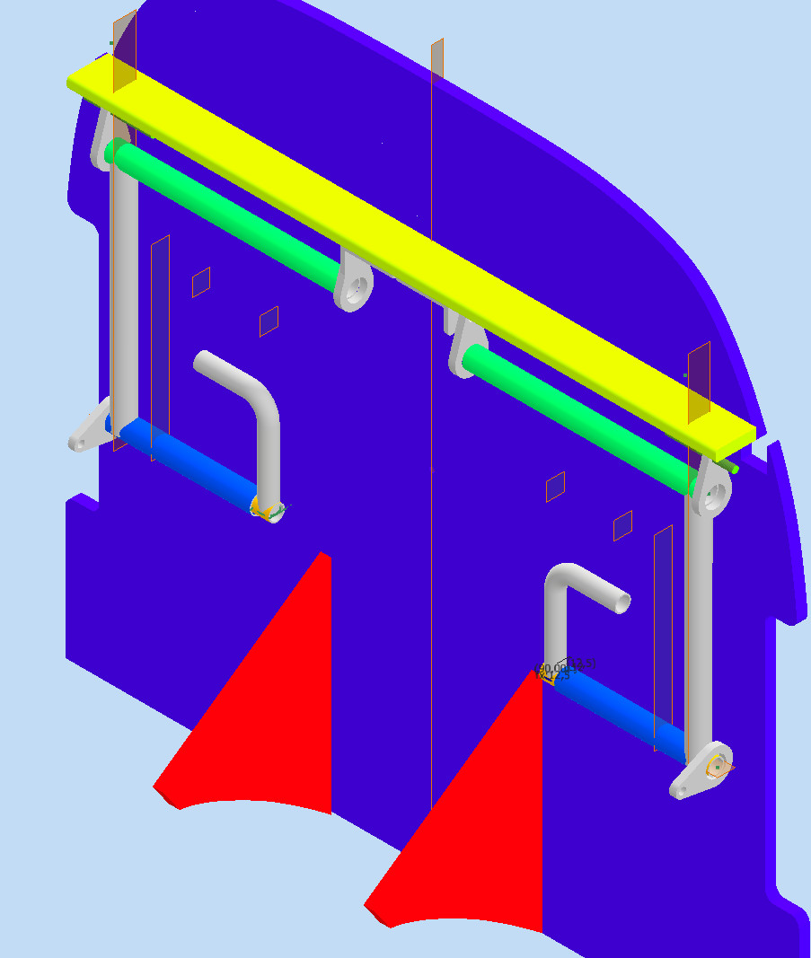
Chapter 08 - 3: Pedals
Material specs:
Material specs:
- Diameter: 12 mm and 10 mm
- Color: black, silver
- Material: Cold rolled steel
- Surface: bright
- Thickness: 1 mm
- Type: Round tube
- Other properties: Good weldability
- Length: 1.000 mm
- Weight: (net) 270 g / per 1000mm
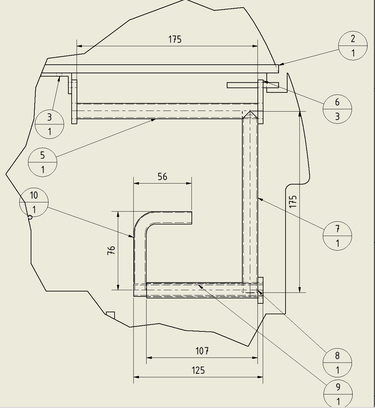
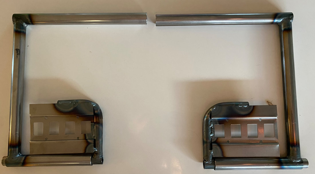
Pedals after TIG welding ready to clean up, paint and install.
Chapter 09 - Main Wing
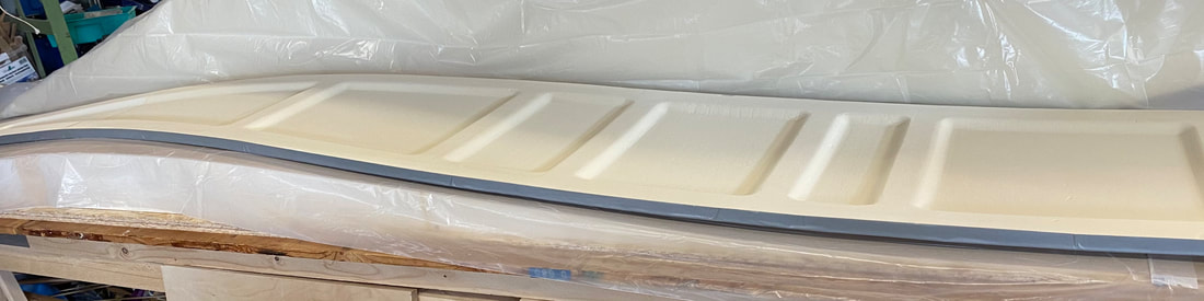
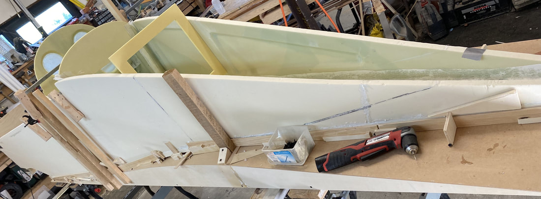
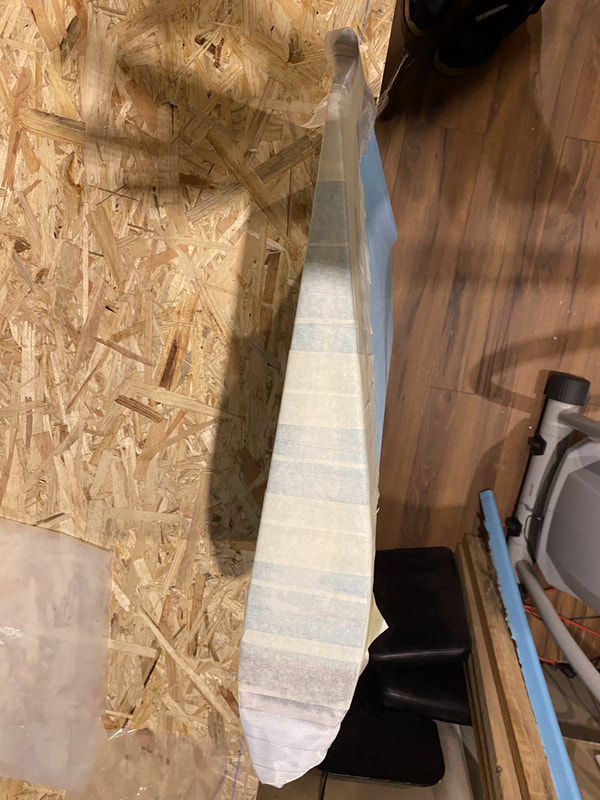
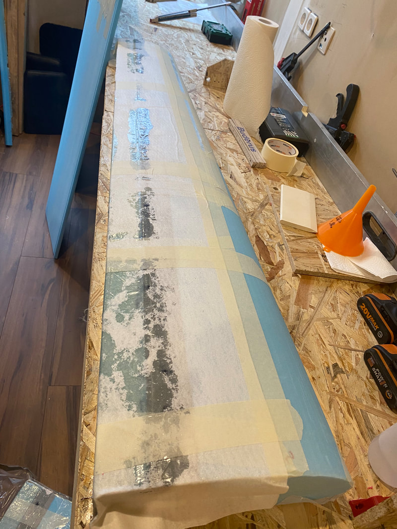
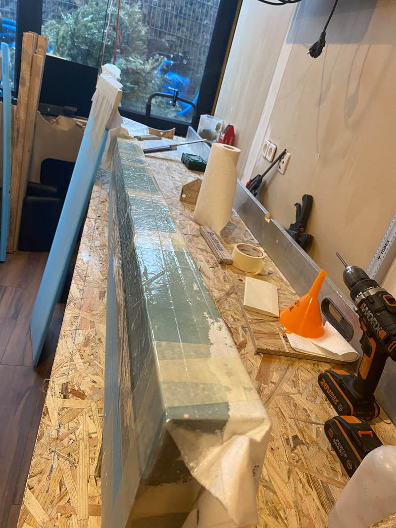
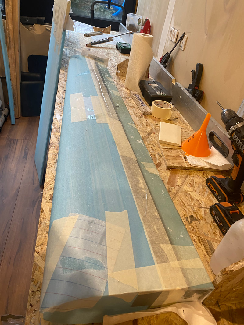
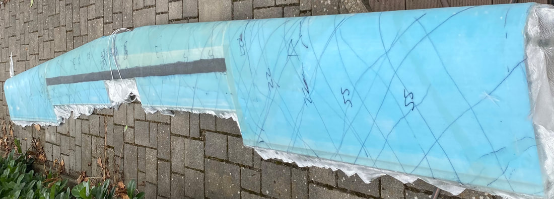
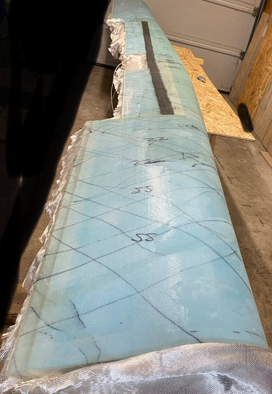
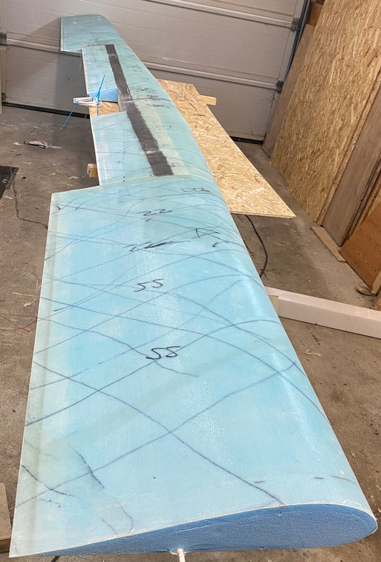
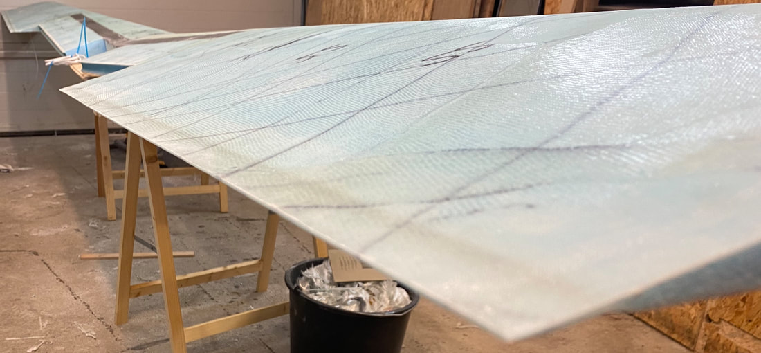
Glassing the ailerons slots on both inboard of main wing with one BID and pulpy on the top. Be aware that the inboard should be placed on the flat table and depress with a weight to prevent twisting of the slots. After that the next challenge will start, to fixed all templates, made from OSB boards, to level each wing unit in the right water level based on the bottom line. If that is done the the whole table need to flip 90 degrees after the wing units are fixed with micro and cure is done! Be excited!
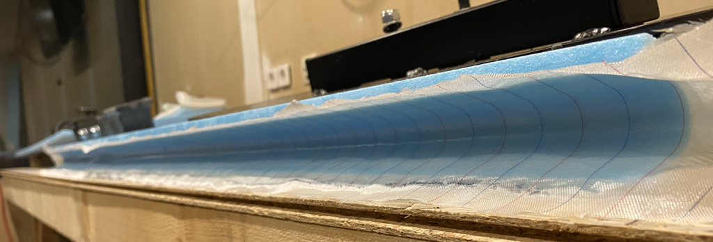
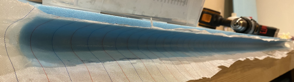
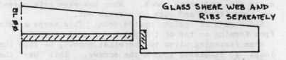
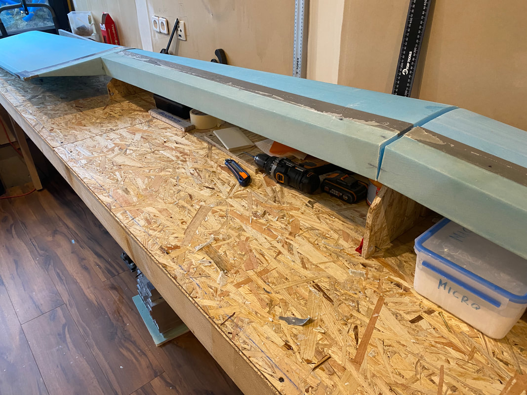
Main wing (Page 9-1): The whole wing fabrication was a ridiculous exercise, especially turning the worktable over to glass the shear web. The problem occurs when constructing the wing shear web in the aileron-cutout area. The web, in a "U" shape, must make a 90-degree turn, forming a flanged rib outboard of the aileron. However, making that 90-degree turn causes the glass shear web tape to bunch up in the corners. Consider the following instead:
First, glass the shear web on the inboard wing foam cores separately and glass the rib on the inboard end of the outboard wing cores. (These pieces can be supported in any way the builder sees fit during glassing.) NOTE: The rib does not extend any closer to the trailing edge than 2" from the finish trim edge. The rib DOES extend to the maximum core thickness, or 2" beyond the shear web flange for construction purposes. Fit some duck tape around to secure from some resin and glass.
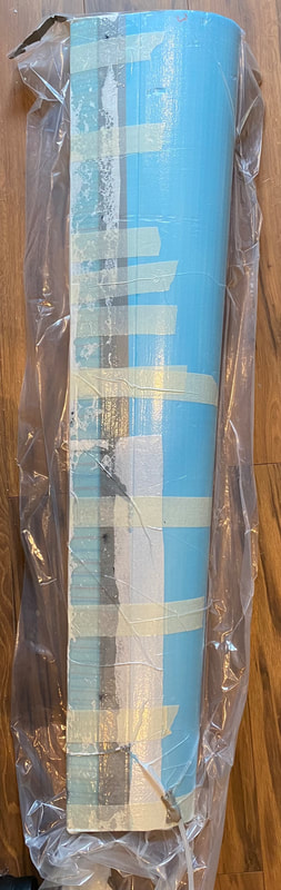
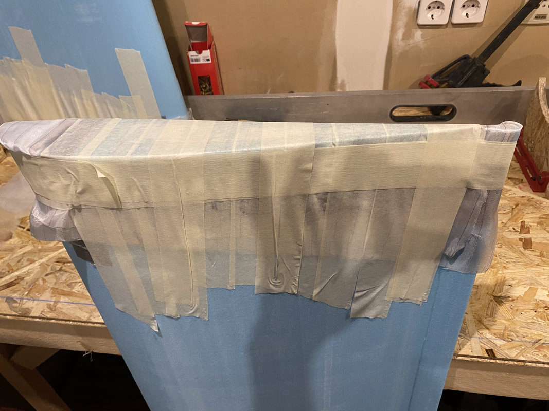
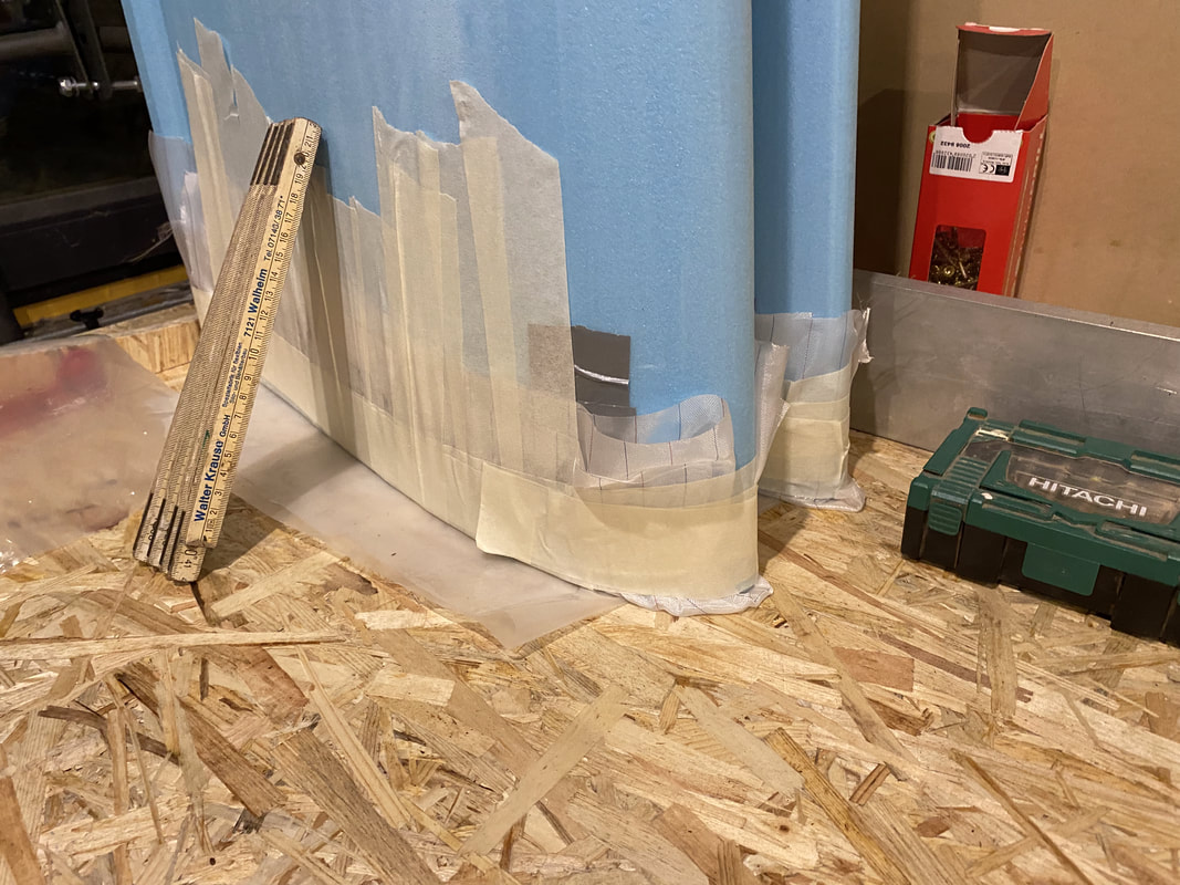
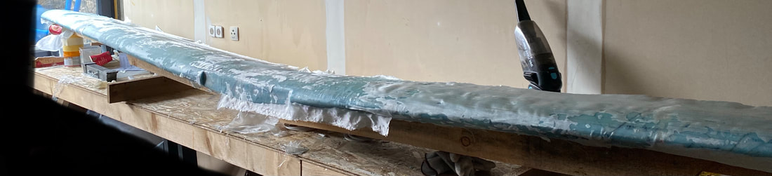
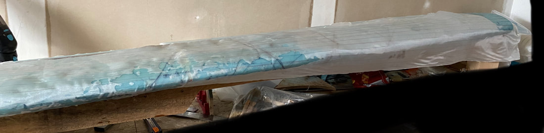
After the glass was placed and covered with Compoflex and ply-eel, both halves were put into the vacuum bag and placed under vacuum for 24 hours.
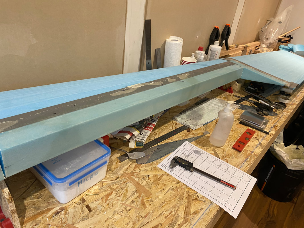
After cure, jig the wing in the supports and join the cores using the standard plans procedures. Add two 4" BID tapes to the vertical face of the shear web and rib.
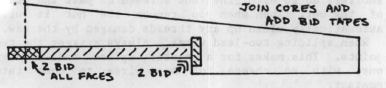
Next, add two 8" BID 45-degree tapes over all butted faces (wraparound top and bottom). To ensure the required torsional stiffness, extend the "C" and "H" spar caps by 4" overall to allow an additional two inches outboard of the rib. This will reinforce the joint between the two flanges and maintain the original integrit
After the main wing was covered with glass, a layer of peel ply was applied.

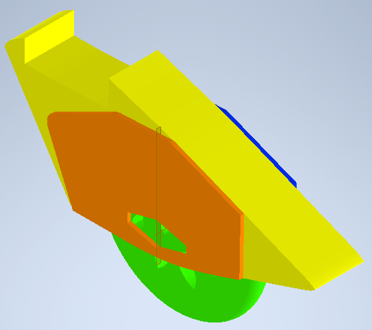
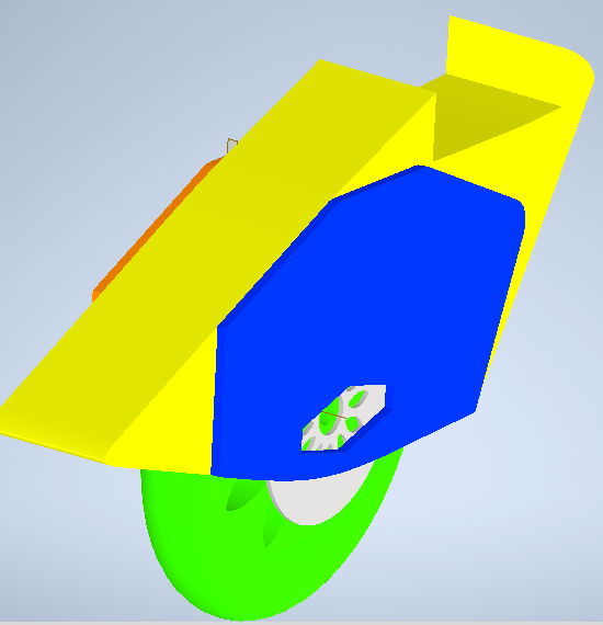
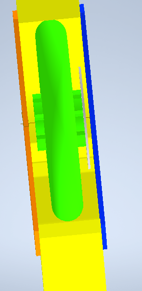
Chapter 20 Large Wheel
In QT#5, Jim Stovekin asked if there were any tires without knobs that fit the large Quickie wheels. The 4.00-5 size tires could not be easily found in this hemisphere. At Kerrville, Gene Sheehan said that 11.400x5 tires were approximately the same size and could be used. Actually, it is smaller than the Quickie tundra tire and has an aircraft rib design and is manufactured by Cheng Shin. These tires are standard on Eipper and other ultralights and are available through ultralight dealers, Aliexpress or Ebay.
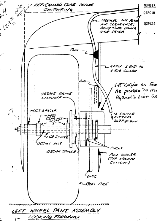
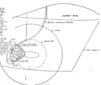
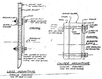
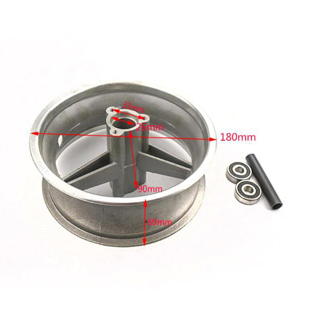
Below the 3D design of wheel and caliper details for the Q1 wheel pant assembly. The caliper will come from mountain bike brake supplier, the disc diameter go up to 180 mm.
In QT#5, Jim Stovekin asked if there were any tires without knobs that fit the large Quickie wheels. The 4.00-5 size tires could not be easily found in this hemisphere. At Kerrville, Gene Sheehan said that 11.400x5 tires were approximately the same size and could be used. Actually, it is smaller than the Quickie tundra tire and has an aircraft rib design and is manufactured by Cheng Shin. These tires are standard on Eipper and other ultralights and are available through ultralight dealers, Aliexpress or Ebay.
Below the 3D design of wheel and caliper details for the Q1 wheel pant assembly. The caliper will come from mountain bike brake supplier, the disc diameter go up to 180 mm.
|
|
|
|
|
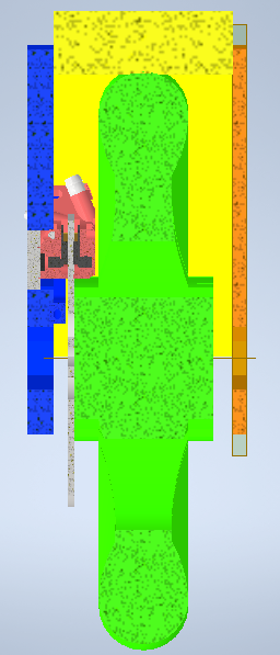
Below the Pant Assembly view with break caliper detail view from the Q2.
|
|
|
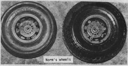
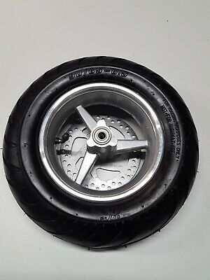
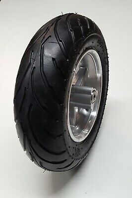
Please find below my choice for the wheels.
Front wheel complete with tire 90/65/6,5 , tube, 3 spoke rim in silver and brake disk
Front wheel complete with tire 90/65/6,5 , tube, 3 spoke rim in silver and brake disk
- Tire type: road tires 90/65 - 6.5; tire width pumped 84 mm
- Tread: road tread
- Speed index: J (up to 100 km/h)
- Size: 90/65 - 6,5
- Alloy rim: Alloy rim 6,5 inch front; Rim width 68 mm
- Axle diameter: 10 mm; axle length 85 mm
- Outer diameter: approx. 29.5 cm
- Perforated brake disc, diameter 140 mm; inner diameter 29 mm;
- Tire with tube (curved valve), matching tube is included
- Weight. 1.8 kg per unit
|
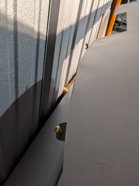
Page 22 Join the tail to the fuselage
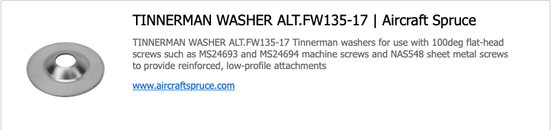
Tinnerman washers |
|
|
|
